Our Project Journey

TU (Hmawbi)
Electrical Power Engineering
Project Showcasing
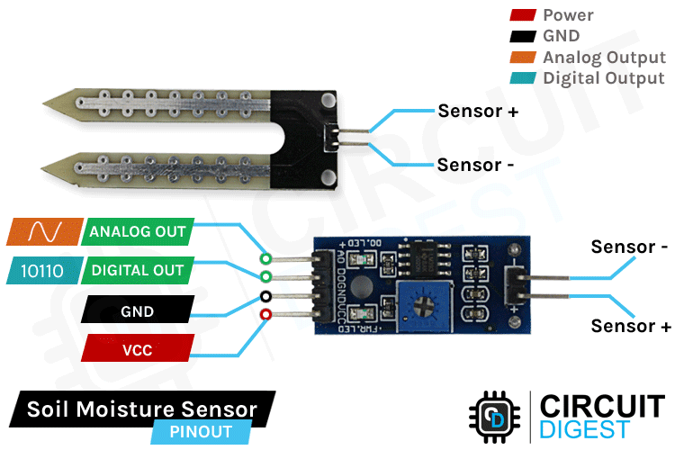
Soil Moisture Sensor
The Soil Moisture Sensor Module is used to measure the amount of
water (moisture) present in the soil. It helps determine whether the
soil is dry, moist, or wet. This information is important for
automatic irrigation systems in greenhouses, as it ensures plants
get the right amount of water — not too much and not too little.
This electronic component is used to measure the water content in
soil or other similar media. It has two large prongs that are
inserted directly into the soil.The sensor works by measuring the
electrical conductivity between the two conductive strips on the
prongs. More water in the soil means higher conductivity, and the
sensor outputs a different electrical signal. This signal can then
be read by a microcontroller, like an Arduino, to determine how wet
the soil is.
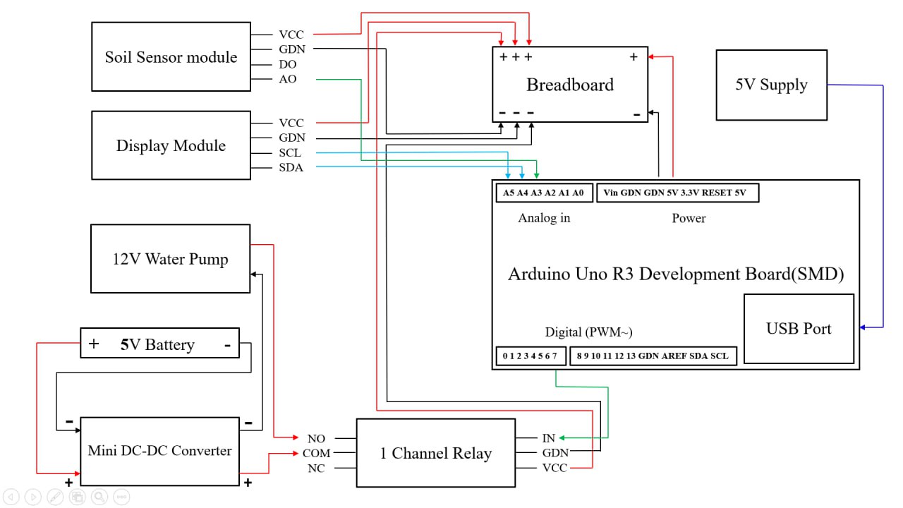
Connection of Soil Sensor and it’s Circuit Board
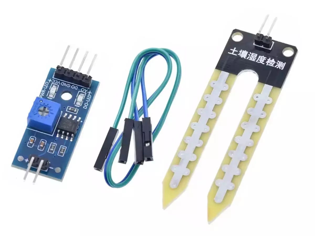
This device is made up of two main pieces that work together to check how much water is in the soil. The first part is the fork-shaped probe which has two metal lines on it. This part is placed directly into the dirt or plant pot. The second part is the electronic module, which is a small green circuit board. This board reads the signal from the probe and converts it into a usable number. The board usually has a small blue knob, called a potentiometer, that lets you adjust the water level that triggers a signal. This sensor is commonly used in smart gardening to build simple systems that water plants when the soil gets too dry.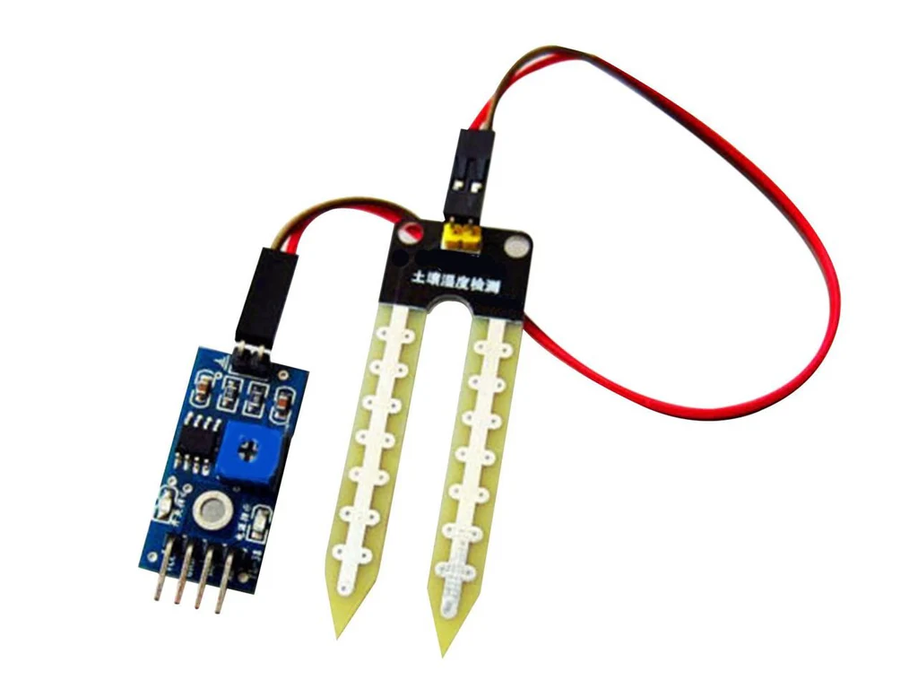
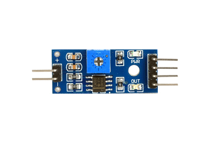
Circuit Board of Soil Moisture Sensor
This small circuit board is the control unit for the soil moisture sensor probe seen in the previous image. The board has the electronic parts needed to read the signal from the probe and convert it into a useful output. It features a blue potentiometer, which is a small adjustable dial, that allows the user to set a specific threshold for moisture. When the soil moisture crosses this set point, the board can provide a digital output. It also includes an integrated circuit, usually a comparator chip like the LM393, to handle the signal comparison. This module is essential for making the soil probe functional with microcontrollers like Arduino.Components of the Sensor
The module mainly consists of two parts :
(a) Probe (Soil Moisture Sensor)
1. The probe is made of two conductive metal rods (usually copper or stainless steel). 2. It is inserted into the soil, and it measures the resistance or conductivity between the two rods. 3. When the soil has more water, it conducts electricity better (low resistance). 4. When the soil is dry, it resists electricity (high resistance).(b) Electronic Module (Control Board)
1. The probe is made of two conductive metal rods (usually copper or stainless steel). 2. It is inserted into the soil, and it measures the resistance or conductivity between the two rods. 3. When the soil has more water, it conducts electricity better (low resistance). 4. When the soil is dry, it resists electricity (high resistance).
Working Principle
When the probe is inserted into the soil :
Wet soil → more conductivity → lower resistance → higher analog
output voltage.
Dry soil → less conductivity → higher resistance → lower analog
output voltage.
The control board reads this data and sends the signal to a
microcontroller (like Arduino). Based on the reading, the system
can turn on or off a water pump automatically.