Our Project Journey

TU (Hmawbi)
Electrical Power Engineering
Project Showcasing
Ultrasonic Sensor
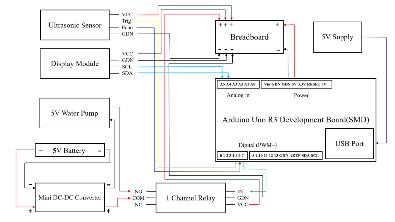
In this Smart Greenhouse project, HC-SR04 ultrasonic sensor module
is used as a water level sensor. The HC-SR04 Ultrasonic Sensor is a
distance measuring sensor that uses sound waves (ultrasonic waves)
to detect how far an object is. It works on the same principle as
how bats detect objects in the dark—by sending sound waves and
measuring the echo time. In a greenhouse project, it can be used to
measure water levels, detect object distance, or even monitor plant
growth height.
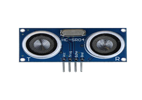
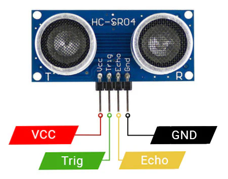
A common four-pin ultrasonic sensor module, often used for distance
measurement in robotics and other electronics projects. The sensor
features four main connections: VCC (Voltage Common Collector, the
power supply pin), Trig (Trigger, the pin used to initiate the
ultrasonic burst), Echo (the pin that provides a pulse whose width
is proportional to the distance measured), and GDN (Ground, the
common reference point for the circuit). These four pins are
essential for connecting the module to a microcontroller, which
manages the timing of the trigger pulse and interprets the resulting
echo pulse to calculate the distance to an object.

Components of the HC-SR04 Ultrasonic Sensor The HC-SR04 module mainly consists of four main components :
1. Transmitter (Trig Pin)
2. Receiver (Echo Pin)
3. Control Circuit
4. Microcontroller Interface Pins
Working Principle :
1. The microcontroller (like Arduino) sends
   a 10 µs pulse to the Trig pin.
2. The sensor emits 8 ultrasonic bursts at
   40 kHz.
3. These waves hit an object and bounce back
   to the receiver.
4. The sensor measures the time taken for
   the echo to return.
5. Distance is calculated using the formula
   as shown in picture.