Our Project Journey

TU (Hmawbi)
Electrical Power Engineering
Project Showcasing
Light Sensor
A Light Sensor Module is an electronic device that detects the
intensity of light in the surrounding environment. It converts light
energy into an electrical signal that can be read by a
microcontroller (like Arduino or Raspberry Pi). In greenhouse
projects, this sensor helps monitor sunlight levels to maintain
optimal lighting conditions for plant growth. When sunlight
decreases (for example, in the evening or during cloudy weather),
the sensor detects the drop in light intensity. The system (e.g.,
Arduino) then automatically activates artificial lights to maintain
the proper brightness level for plant photosynthesis.
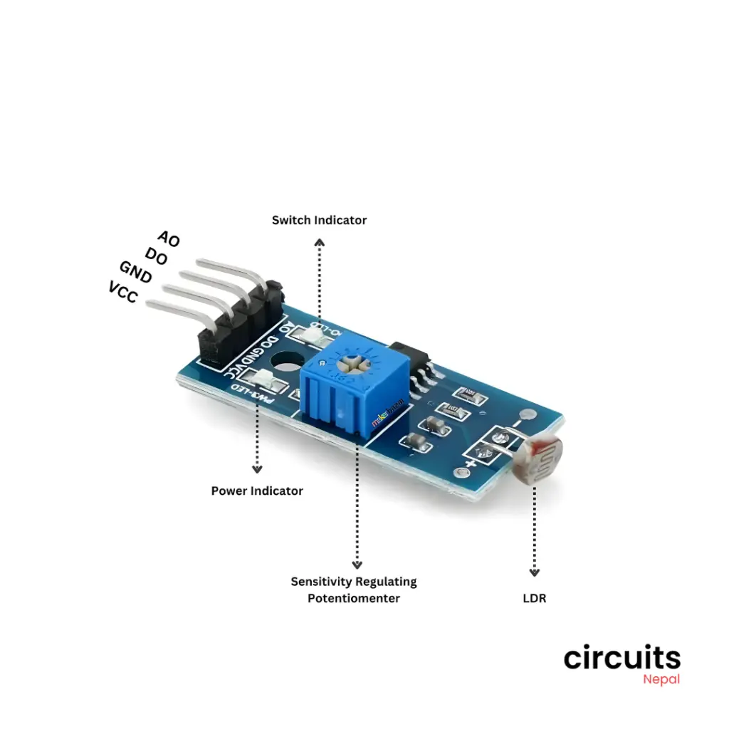
Light Sensor Module with four distinct connection pins, which are
standard for many basic electronic sensor components. The VCC pin is
for the power supply voltage (often 5V or 3.3V), while GDN (likely
labeled as GND on the actual module) represents the Ground
connection, completing the power circuit. The output pins provide
data: DO stands for Digital Output, which typically provides a
simple HIGH or LOW signal based on a set threshold of light
intensity, making it suitable for simple on/off control like a basic
light-activated switch. Finally, AO stands for Analog Output, which
provides a variable voltage proportional to the actual measured
light intensity, offering a more nuanced reading for applications
requiring continuous light measurement.
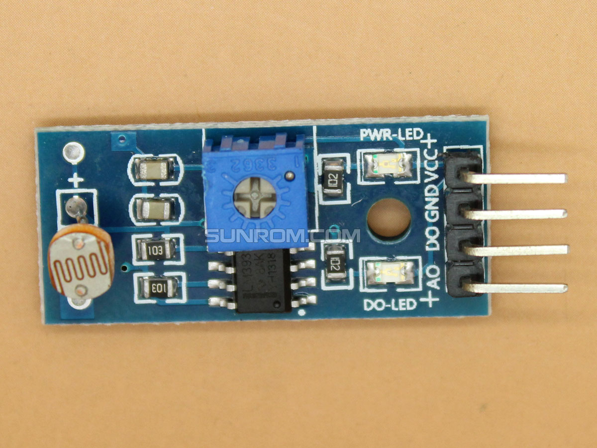
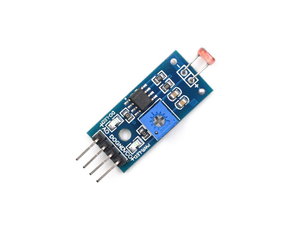
Main Components of Light Sensor Classification of main components in the light sensor include the following types of components:
1. Photoresistor (LDR – Light Dependent Resistor)
2. Resistor (Fixed Resistor)
3. Comparator IC (e.g., LM393)
4. Potentiometer (Variable Resistor)
5. Power Indicator LED and Output LED
6. Output Pins
Uses :
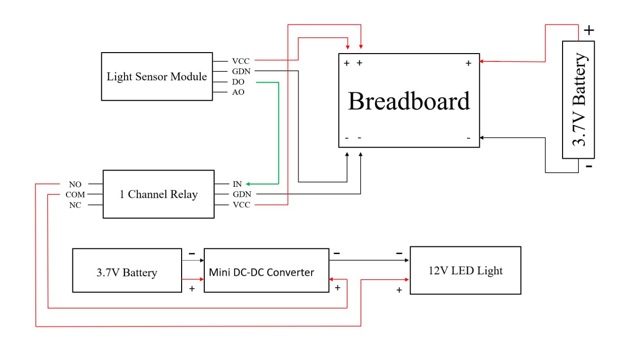
In a greenhouse, plants need an appropriate amount of sunlight for healthy growth. The Light Sensor Module is used to :
1. Monitor Light Intensity: Detect whether plants are
   receiving sufficient light.
2. Control Artificial Lighting: Automatically turn ON
   grow lights when natural sunlight is low and turn them
   OFF when sunlight is adequate.
3. Data Logging: Record daily light levels to analyze
   growth conditions.
4. Energy Efficiency: Helps maintain ideal lighting using
   minimal electricity.