Our Project Journey

TU (Hmawbi)
Electrical Power Engineering
Project Showcasing
Temperature Sensor
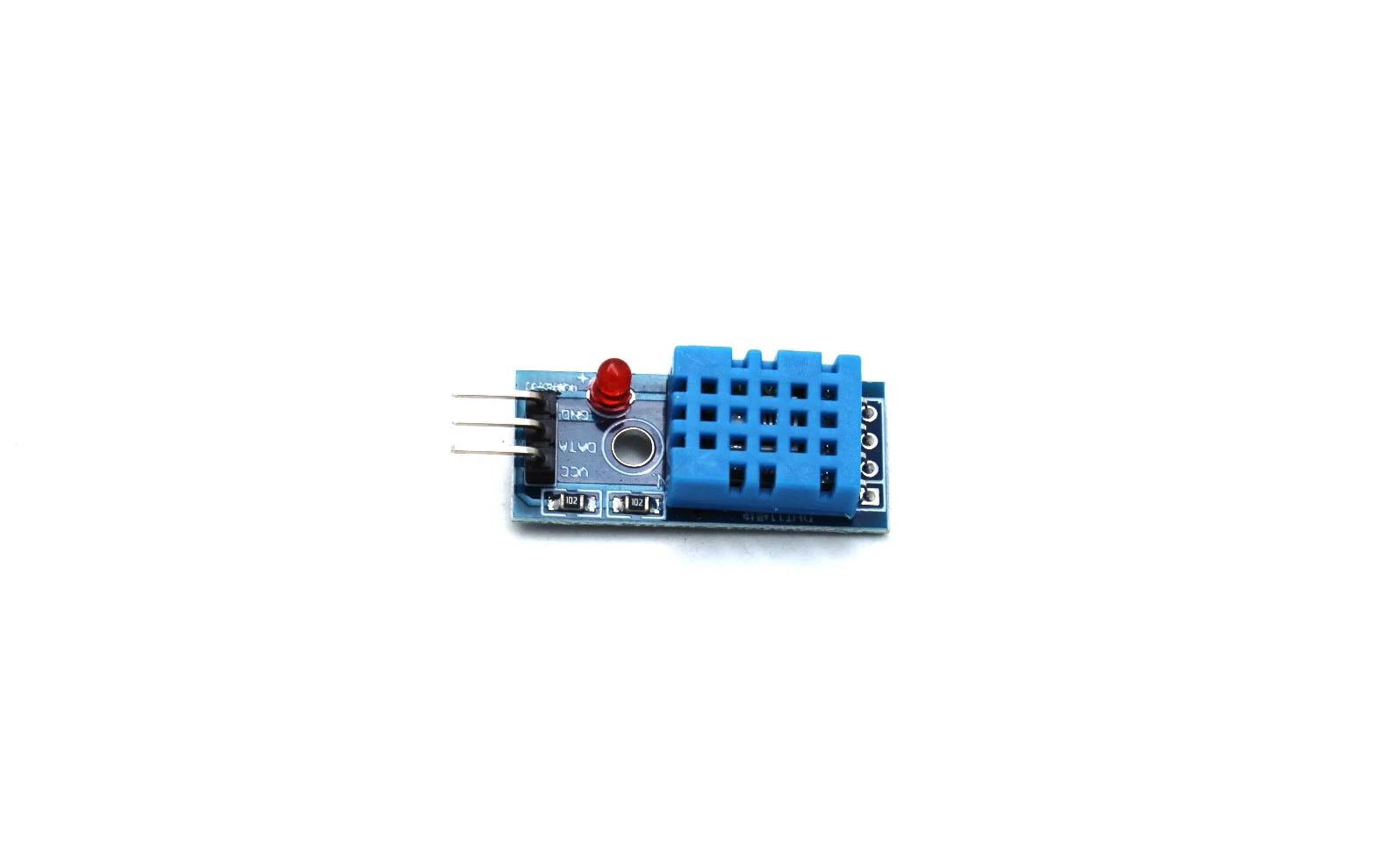
Module DHT11 (Temperature and Humidity Sensor) The DHT11 is a
digital sensor used to measure temperature and humidity. It is
widely used in environmental monitoring projects such as
greenhouses, weather stations, and automatic climate control systems
because it is simple, low-cost, and easy to interface with
microcontrollers like Arduino or Raspberry Pi. The DHT11 module is a
simple and effective sensor for monitoring temperature and humidity
in greenhouse environments. Although it has limited accuracy and
speed, its low cost, easy operation, and digital output make it an
ideal choice for academic and small-scale greenhouse automation
projects.
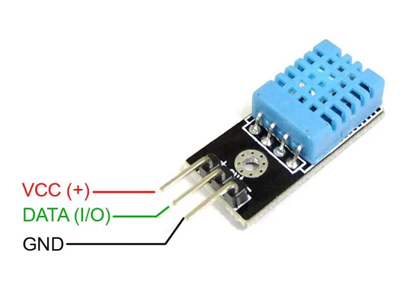
Temperature Sensor module, depicted as a simple block with three
primary external connections. The top pin is labelled VCC, which
stands for Voltage Common Collector, indicating the connection point
for the positive power supply, typically between 3.3V and 5V for
many common sensors. The bottom pin is labelled GDN, short for
Ground, serving as the reference point for the circuit and the
negative connection for the power supply. Sandwiched between the
power and ground is the crucial IN pin, which represents the
Input/Output signal line, and is where the temperature reading,
often as an analog voltage or digital signal, would be measured or
transmitted to a microcontroller. This simple three-pin
configuration is standard for many basic sensor modules used in
hobbyist and educational electronics projects.
Components of the Temperature Sensor Module (DHT11 Module) The DHT11 module mainly consists of the following parts:
1. DHT11 Sensor (Blue Component)
2. Signal Processing IC (Inside the Sensor)
3. Resistor (on the module board)
4. PCB Board & Connector Pins
Working Principle of DHT11 Module The DHT11
1. When humidity increases, the resistance of the humidity
   sensor changes, and the IC converts this change into a
   humidity value.
2. The thermistor detects temperature by its resistance change
   with heat.
3. Both readings are processed and sent as a digital signal
   through the data pin.
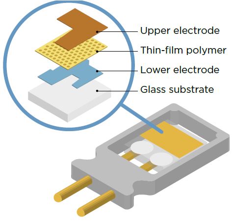
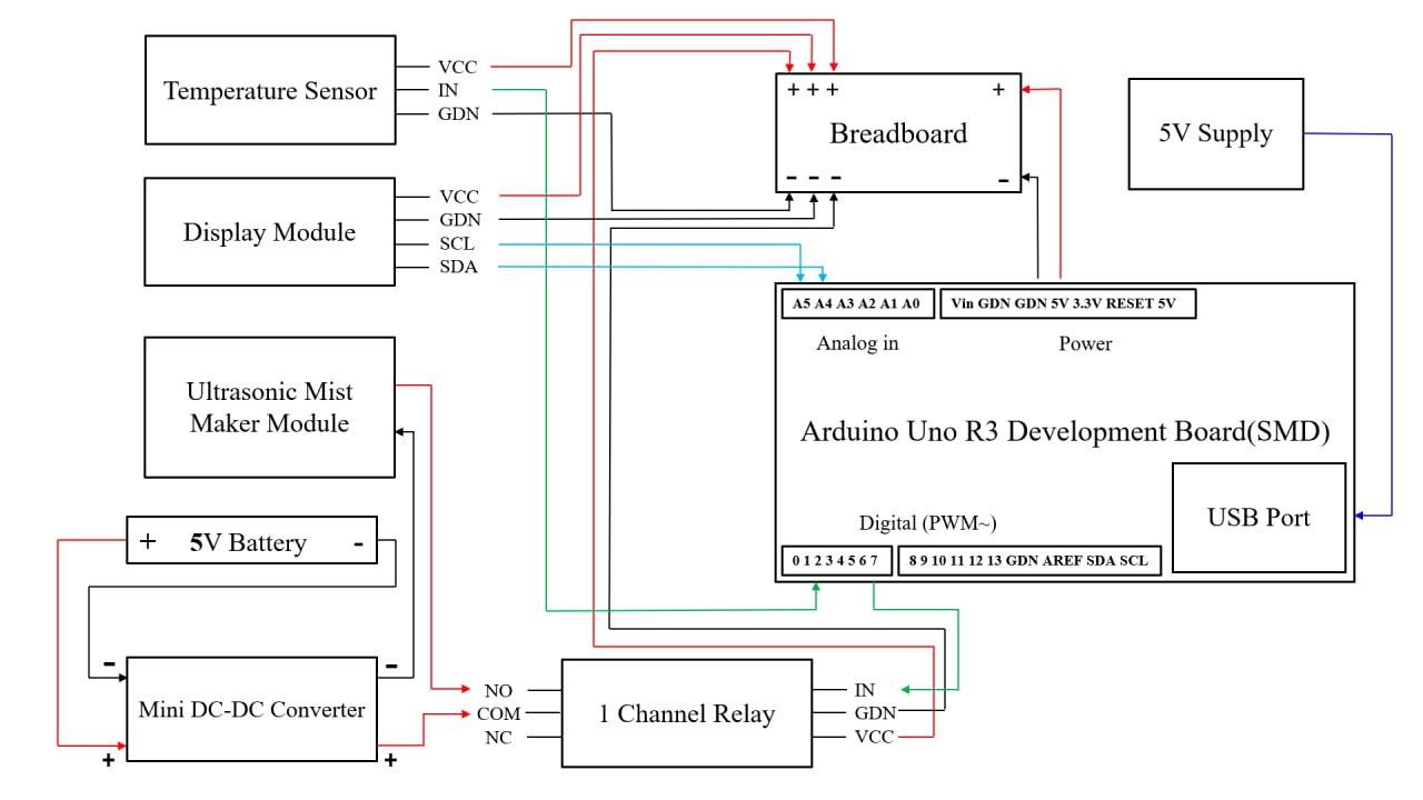
Fig : Circuit Diagram of Smart Temperature Control System
Circuit Diagram of Smart Temperature Control System
1. The system uses a Breadboard as a central point for distributing power
   to the Temperature Sensor and Display Module.
2. The Arduino Uno R3 Development Board acts as the main controller for
   the entire electronic circuit.
3. The Temperature Sensor provides an analog signal input to the
   Arduino Uno R3 on pin A0.
4. A 1 Channel Relay is used to control the power to the Ultrasonic
   Mist Maker Module acting as a switch.
5. The Display Module communicates with the Arduino Uno R3 using two wires
   a standard protocol called I2C on pins A4 and A5.
6. The Ultrasonic Mist Maker Module is powered by a separate 5V Battery
   to prevent high current draw from affecting the Arduino.
7. A Mini DC-DC Converter is used between the 5V Battery and the
   Mist Maker possibly for voltage regulation or isolation.
8. The Mist Maker is connected to the Relay's Normally Open (NO)
   and COM terminals meaning the mist maker is off until the Relay
   is activated by the Arduino.